State Store in Streaming Systems
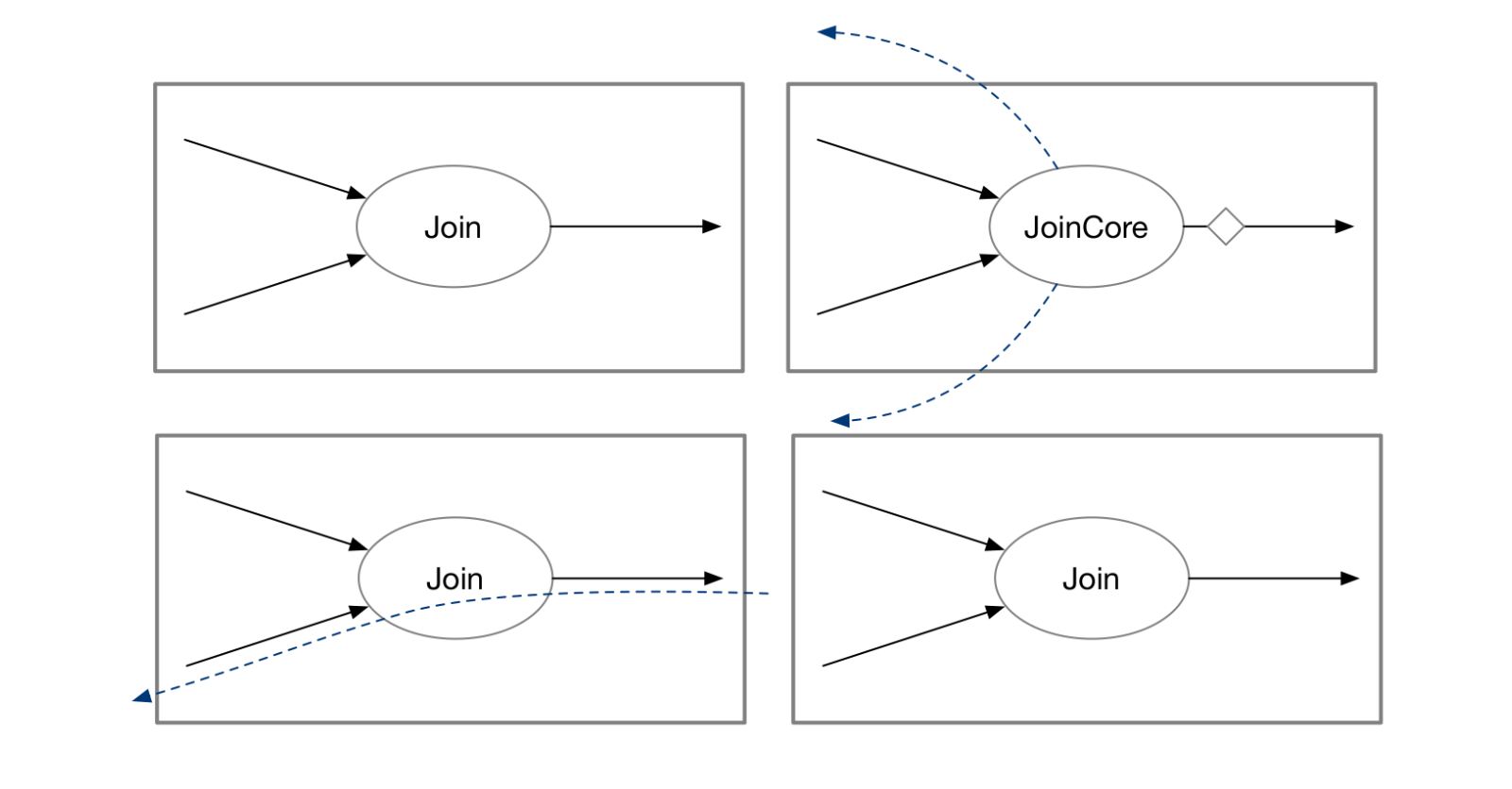
Table of Contents
- Introduction
- Full State — Operators Maintain Their Complete State
- Shared State — Sharing State Among Operators
- Partial State — Operators Store Only Partial Information
- References
Introduction
Data processed by a stream processing system is often unbounded: data keeps flowing in from the data source, and users need to see the real-time results of SQL queries. At the same time, compute nodes may encounter errors or failures, and the system may need to scale them up or down in real time according to demand. Throughout this process, the system must efficiently transfer intermediate computation state between nodes and persist it in external systems to keep computation running without interruption.
This blog post introduces three approaches to storing state in stream processing systems from industry and academia: storing complete state (e.g., Flink), storing shared state (e.g., Materialize and Differential Dataflow), and storing partial state (e.g., Noria (OSDI ‘18)). Each approach has its own advantages and can offer insights into the development of future stream processing engines.
Assume there are two tables in a shopping system:
visit(product, user, length)represents the number of seconds a user views a product.info(product, category)represents the category to which a product belongs.
Now we want to answer this question: What is the longest time that a user has viewed a product in a given category?
CREATE VIEW result AS
  SELECT category,
       MAX(length) as max_length FROM
  info INNER JOIN visit ON product
  GROUP BY category
This query contains a join between two tables and an aggregation. The following discussion is based on this query.
Assume the current state of the system is:
info(product, category)
Apple, Fruit
Banana, Fruit
Carrot, Vegetable
Potato, Vegetable

visit(product, user, length)
Apple, Alice, 10
Apple, Bob, 20
Carrot, Bob, 50
Banana, Alice, 40
Potato, Eve, 60
Under this scenario, the query result should be:
category, max_length
Fruit, 40
Vegetable, 60
The Fruit category was viewed by users for a maximum of 40 seconds (corresponding to Alice’s visit to Banana); the Vegetable category was viewed for a maximum of 60 seconds (corresponding to Eve’s visit to Potato).
In a conventional database system, this query typically produces the following execution plan (ignoring optimizer choices):
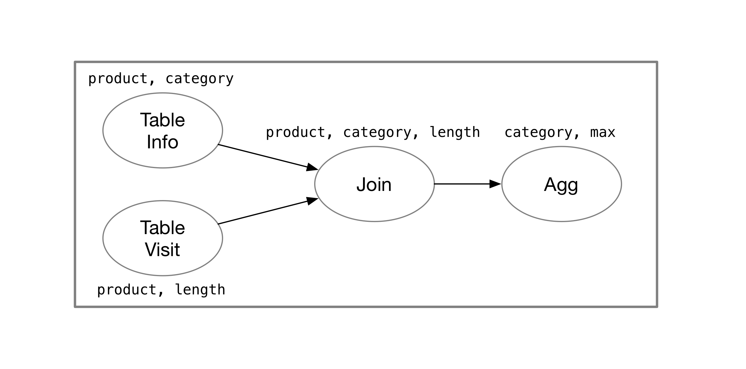
The execution plan of a stream processing system is not significantly different from that of a conventional database system. The following sections explain how various stream processing systems represent and store intermediate computation state.
Full State — Operators Maintain Their Complete State
A stream processing system such as Flink persists the complete state of each operator and propagates data updates among operators in the stream computation graph. This state-storage model is intuitive. In a system like Flink, the SQL query described earlier would produce this computation graph:
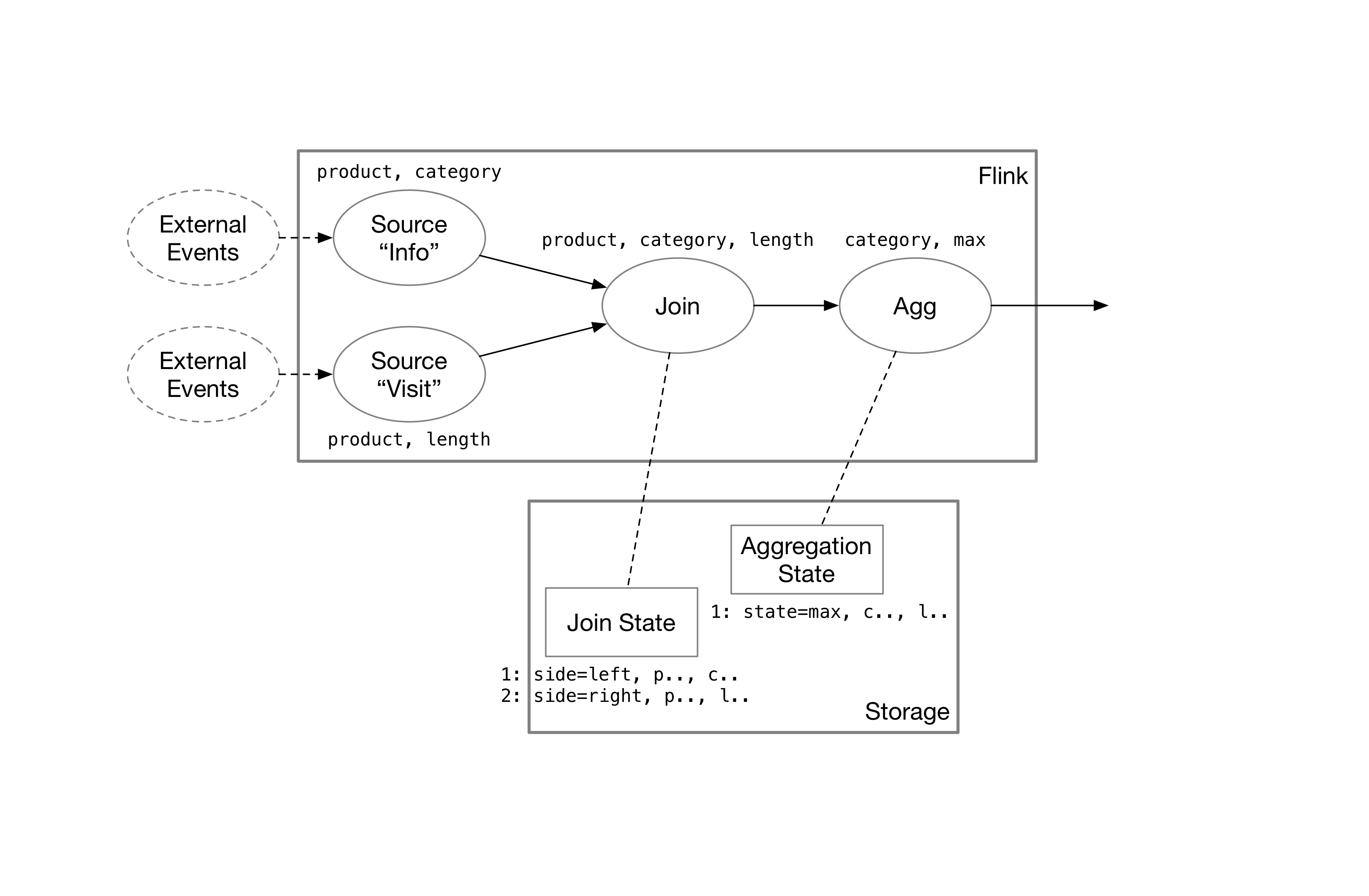
The data sources emit messages that add or remove rows. As these messages pass through the stream operators, they are transformed into the desired results.
State Storage of Join State
When messages from a data source enter the system, the first operator they encounter is the join operator. Let’s revisit the join condition in the SQL query: info INNER JOIN visit ON product. After receiving a message from the left side, info, the join operator fetches rows from the right side, visit, that have the same product and sends the joined rows downstream. It then records the message from info in its own state. Messages from the right side follow the same process.
For example, suppose the right side, visit, receives a message stating that Eve looked at Potato for 60 seconds (+ Potato Eve 60). If the left side, info, already has four records in its state, the join operator queries it for records where product = Potato and finds that Potato is a vegetable. It then sends Potato, Vegetable, 60 downstream.
The state for the right side, visit, also includes the record Potato -> Eve, 60. As a result, if the left side, info, changes, the join operator can send the corresponding updates to the downstream visit operator.
State Storage of Aggregation State
The messages then pass to the aggregation operator, which groups the data by category and calculates the maximum length for each group.
Some simple aggregations, such as sum, only need to track the current value for each group. When the operator receives an insert message from upstream, it increases the sum by the corresponding value. When it receives a delete message, it decreases the sum. Therefore, aggregations such as sum and count (without distinct) require very little state.
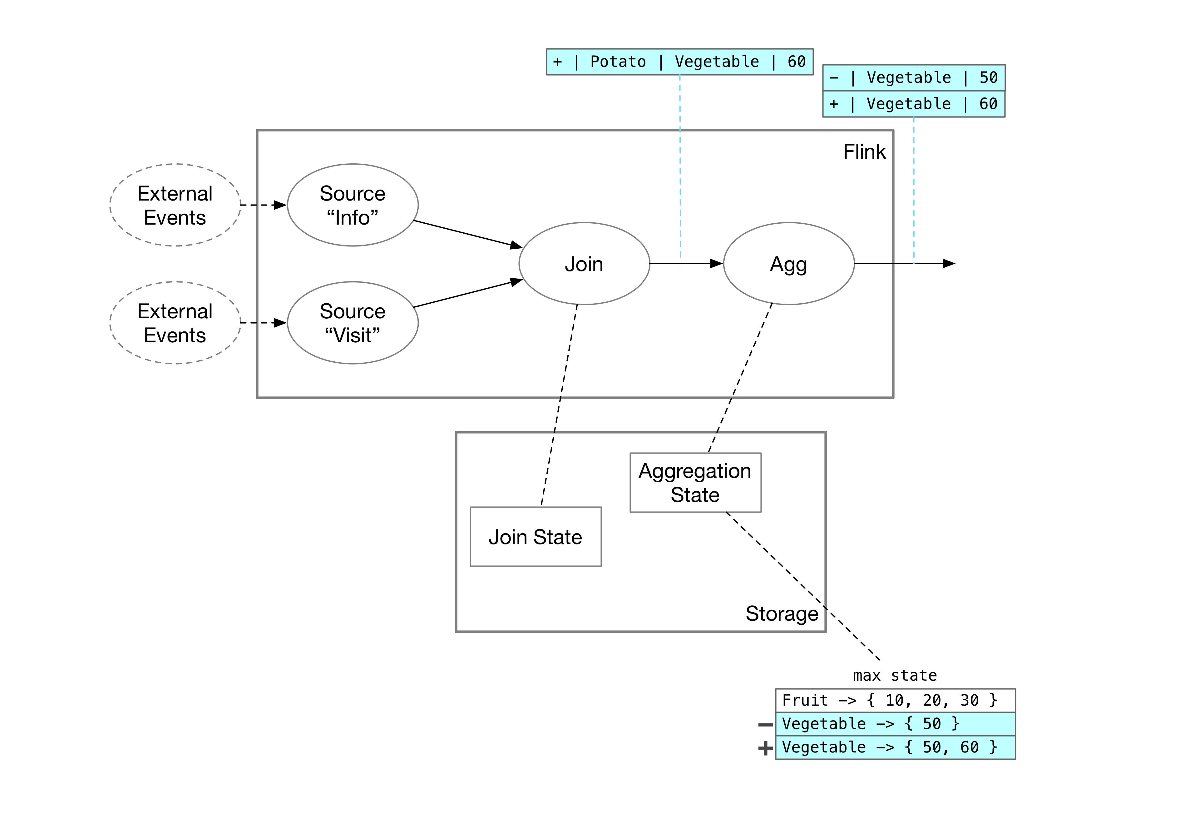
For the max aggregation, however, we cannot record only the maximum value. If a delete message arrives from upstream, the max state must send the second-largest value downstream as the new maximum. If it stored only the maximum, it could not determine the second-largest value after removing the maximum. Therefore, the aggregation operator must store the complete data for each group. In our example, AggMaxState currently stores the following data:
Fruit -> { 10, 20, 30, 40 }
Vegetable -> { 50 }
If the aggregation operator receives an insert message, Potato, Vegetable, 60, from the upstream join operator, it updates its state:
Fruit -> { 10, 20, 30, 40 }
Vegetable -> { 50, [60] }
It also sends the update for the Vegetable group downstream:
DELETE Vegetable, 50
INSERT Vegetable, 60
The entire process is illustrated in the following diagram:
Summary
Stream processing systems that store complete state typically have these characteristics:
- Messages that indicate data changes (additions and deletions) propagate in one direction through the stream computation graph.
- Stream operators maintain and access their own state. For multi-way joins, the stored state may be duplicated. The shared-state section explains this in more detail.
Shared State — Sharing State Among Operators
We will use shared arrangements in Differential Dataflow (the computation engine underneath Materialize) to explain how shared state is implemented.
Arrange Operators and Arrangements in Differential Dataflow
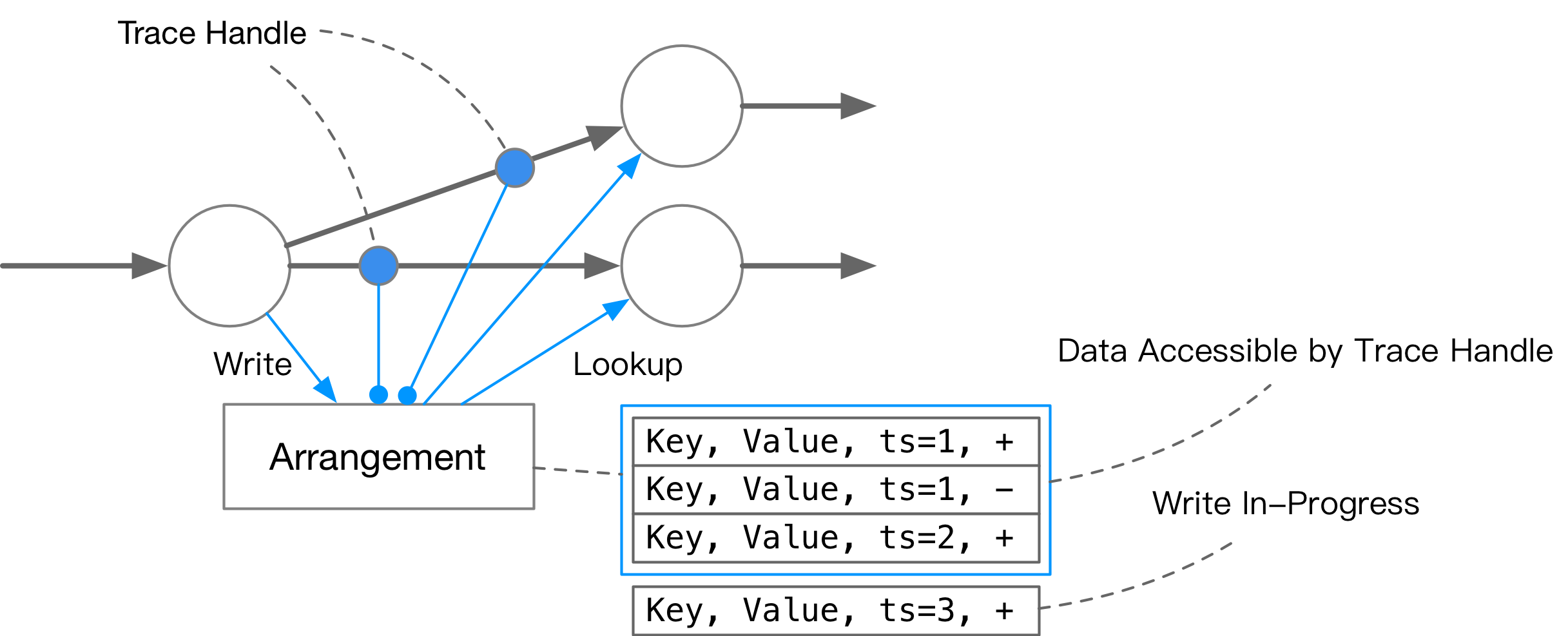
Differential Dataflow uses arrangements to maintain state. In simple terms, an arrangement is a key-value map that supports MVCC. It maps each key to (value, time, diff) tuples. With an arrangement, you can:
- Query the key-value mapping at a given point in time through a handle.
- Query changes to a key over a given period.
- Specify a query watermark and merge or delete historical data that is no longer needed in the background.
In Differential Dataflow, most operators do not have their own state; state is stored in arrangements. Arrange operators can create arrangements, and some operators, such as reduce, maintain arrangements themselves. A Differential Dataflow computation graph passes two kinds of messages:
- Data changes at a particular logical time, represented as
(data, time, diff). This type of dataflow is called aCollection. - Data snapshots represented by arrangement handles. This type of dataflow is called
Arranged.
Each Differential Dataflow operator has specific input and output requirements. For example:
- A map operator (corresponding to an SQL projection) takes a
Collectionas input and produces aCollection. - A
JoinCoreoperator (a stage of a join) takesArrangedinputs and produces aCollection. - A
ReduceCoreoperator (a stage of an aggregation) takes anArrangedinput and producesArrangedoutput.
The following sections introduce the JoinCore and ReduceCore operators in more detail.
From Differential Dataflow to Materialize
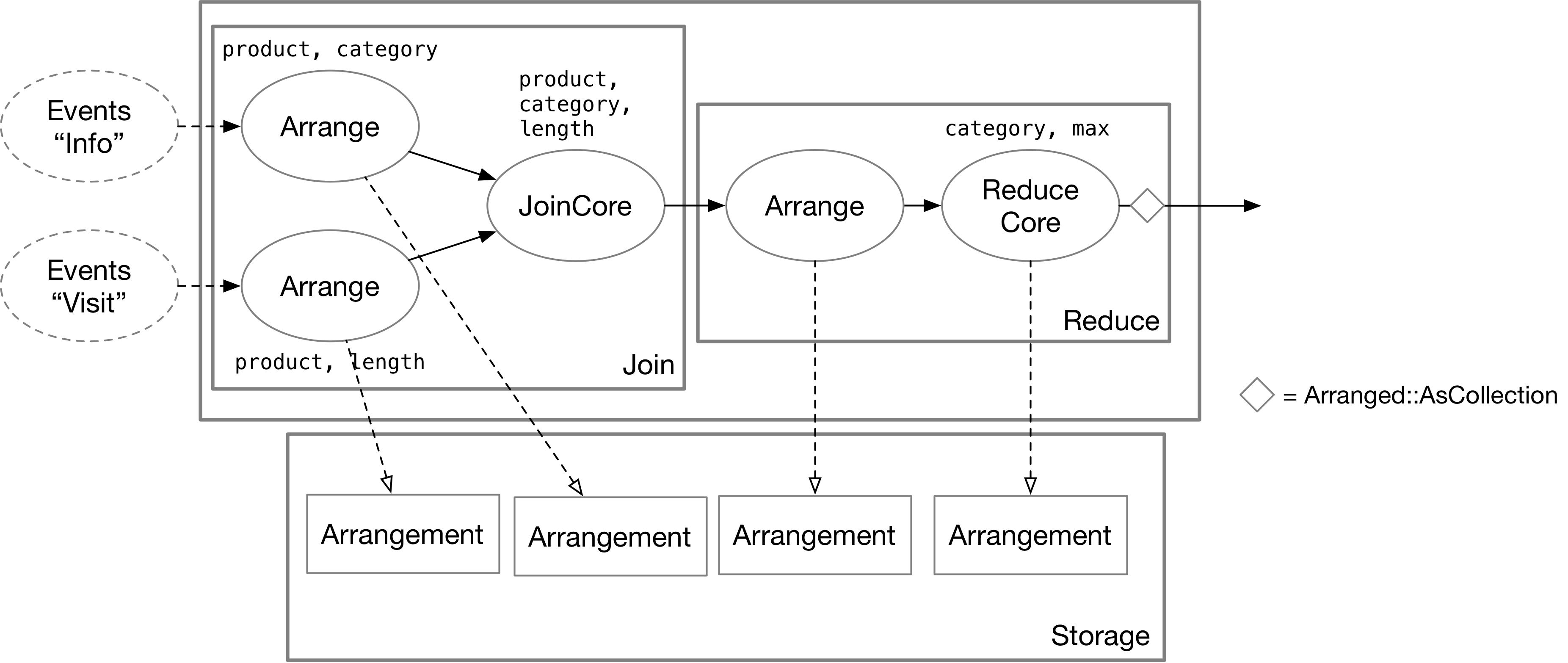
Materialize converts user-submitted SQL queries into Differential Dataflow computation graphs. SQL operations such as joins and GROUP BY often do not correspond to a single Differential Dataflow operator. By following the flow of messages, we can see how Materialize stores state.
State Storage of Join State
The A JOIN B operation in SQL corresponds to three operators in Differential Dataflow: two arrange operators and one JoinCore. The arrange operators persist the state of the two sources separately by join key, storing it in arrangements as key-value pairs. After batching the inputs, the arrange operators send trace handles to the downstream JoinCore operator. The actual join logic runs in JoinCore, which does not store any state itself.
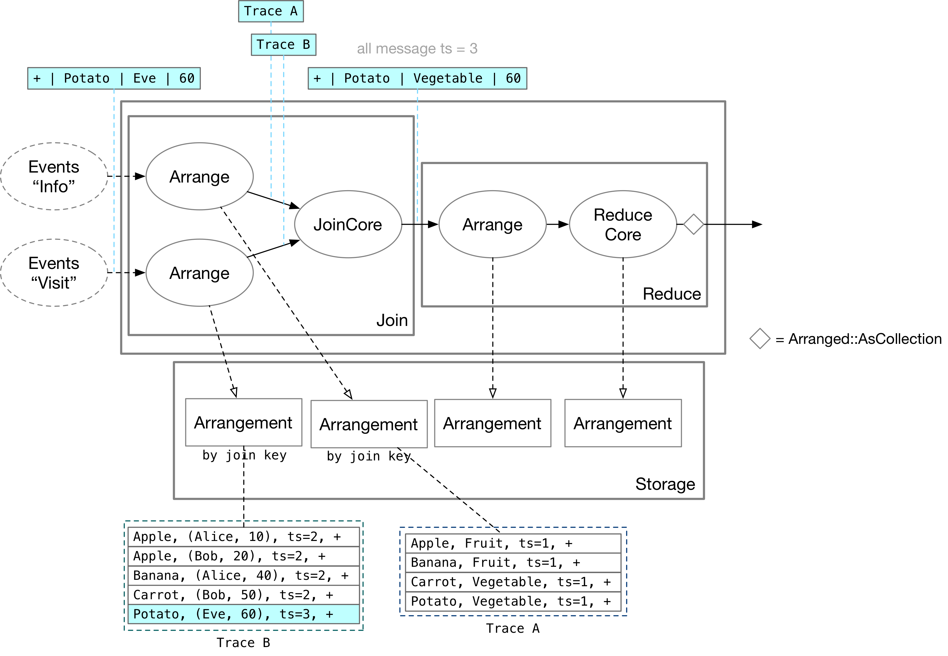
As shown above, suppose a new update arrives on the Visit side: Eve looks at Potato for 60 seconds. The JoinCore operator accesses this update through Trace B and queries rows with product = Potato on the other side, Trace A. It finds that Potato is a vegetable and outputs the change Potato, Vegetable, 60 downstream.
State Storage of Reduce (Aggregation) State
In Differential Dataflow, an SQL aggregation corresponds to a reduce operation. A reduce operation contains two operators: arrange and ReduceCore. The arrange operator stores input data by group key, while ReduceCore maintains an arrangement containing the aggregated results. Finally, the as_collection operation emits those results as a collection.
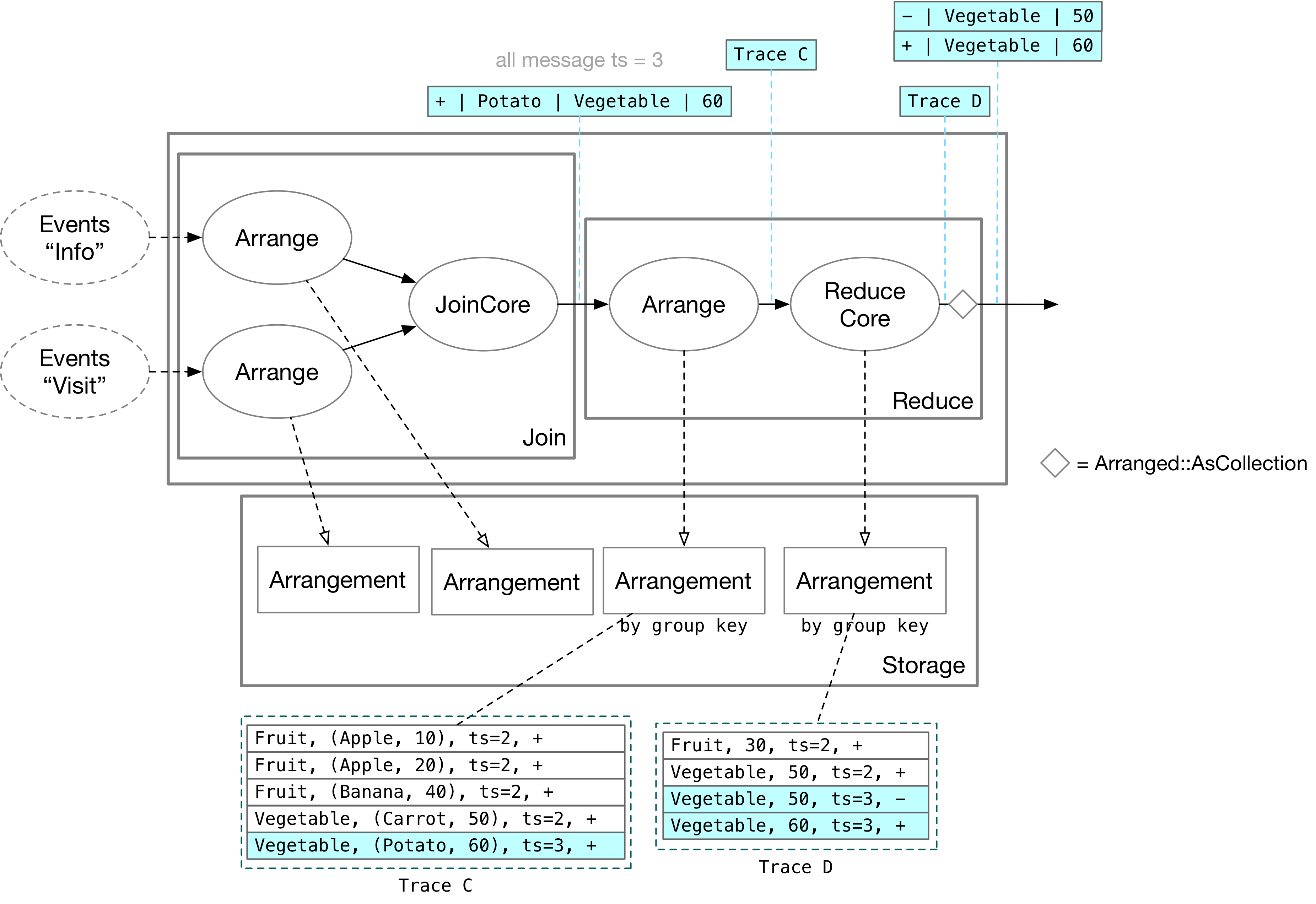
When an update from the join arrives at the reduce operation, the arrange operator first stores it in an arrangement by group key. After receiving Trace C, ReduceCore scans all rows with key = Vegetable and calculates the maximum value. It then updates that value in its own arrangement. The as_collection operation turns Trace D into data updates that other operators can process.
Convenient State Reuse for Operators
Because the operators that store state in Differential Dataflow are separate from those that perform the actual computation, the system can reuse operator state.
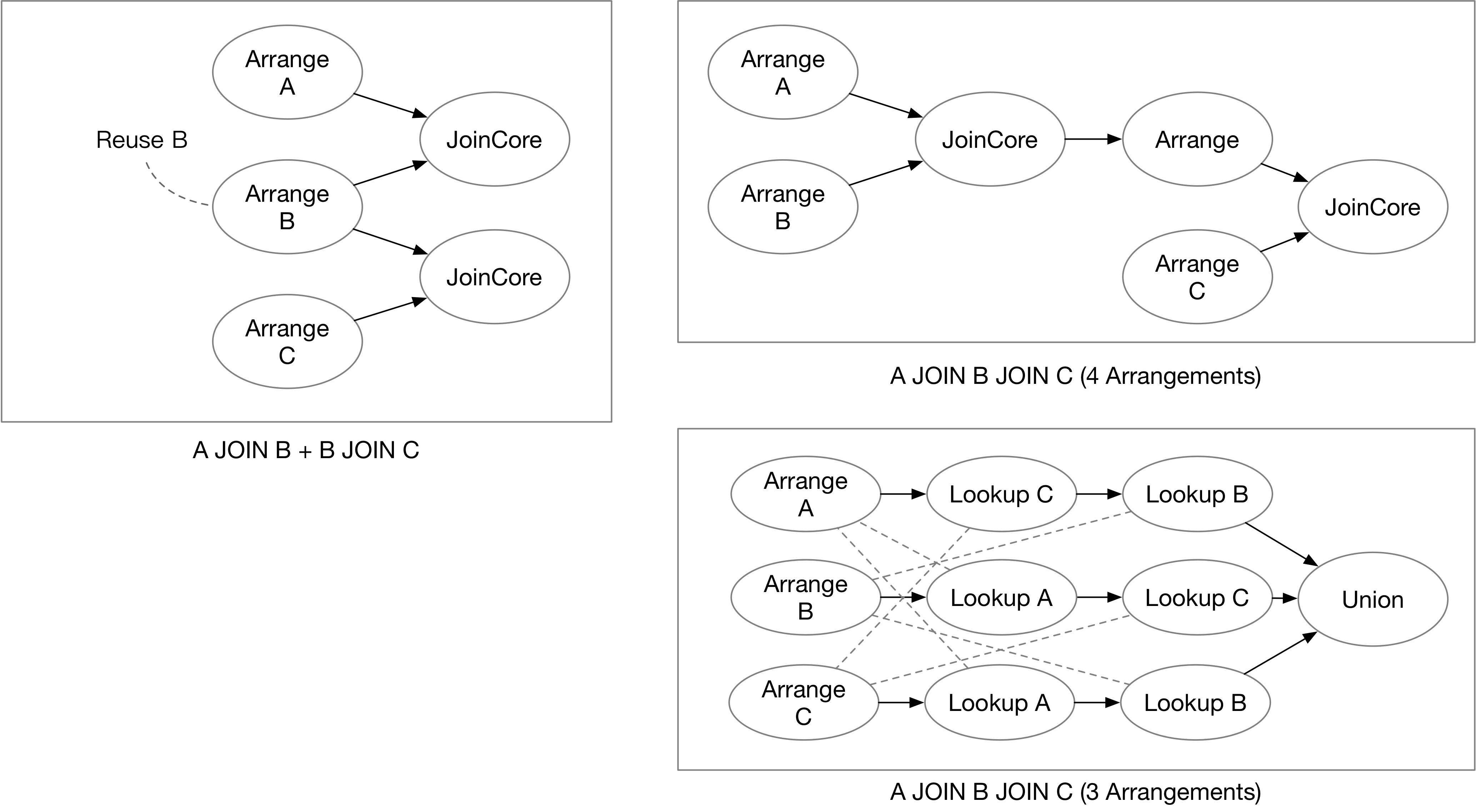
For example, if a user wants to query A JOIN B and B JOIN C at the same time, one possible Differential Dataflow computation graph has three arrange operators and two JoinCore operators. Compared with a stream processing system that stores complete state, this graph avoids duplicating the state of B.
Consider another example: a multi-way join such as SELECT * FROM A, B, C WHERE A.x = B.x and A.x = C.x. If JoinCore operators are used to build the computation graph, state may still be duplicated, requiring four arrangements in total.
Besides using JoinCore as described above, Materialize can implement an SQL join as a delta join. As shown in the figure, the system needs only three arrangements, one each for A, B, and C. Lookup operators then query rows in A that correspond to changes in B and C, and vice versa. Finally, a union produces the join result. A delta join can make full use of existing arrangements, greatly reducing the amount of state required for the join.
Overheads of Shuffling States
In a streaming system, it is often impossible to store and process all data on a single node. Execution therefore generally needs to be partitioned by key across multiple compute nodes. In the two-table join below, the arrangements for tables A and B may be produced on different nodes from those performing the join. The join may also use a different arrangement key or a different number of nodes (different parallelism).
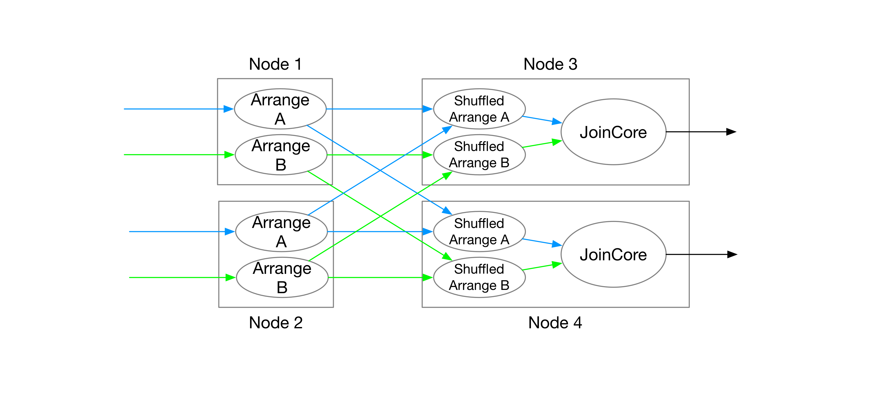
In this case, shuffling arrangements is unavoidable in Differential Dataflow. Each compute node performing a join must create new arrangements for the subset of keys required by its join partition. In general, arranging and computing on different nodes will greatly increase latency, while placing them on a single node cannot fully utilize distributed resources. This creates an inherent tradeoff.
As long as the system ensures that arrangements and joins use the same key distribution and parallelism, state can still be shared without being shuffled.
This blog post previously stated that Differential Dataflow uses remote access for partitioned state. As noted in this GitHub Discussion, that explanation was incorrect and has been fixed.
Summary
In a shared-state streaming system, computation and storage logic are split among multiple operators. Different computation tasks can therefore share storage and reduce the amount of duplicated state. Such a system generally has these characteristics:
- The stream computation graph carries not only data changes but also shared state information, such as Differential Dataflow’s trace handles.
- Accessing state from stream operators incurs some overhead, but state reuse means that less state is stored overall than in a system where each operator stores complete state.
Partial State — Operators Store Only Partial Information
In the Noria system introduced in Noria (OSDI ‘18), data-source updates do not trigger computation, and stream operators do not store complete information.
For example, when a user creates a view (CREATE VIEW result), the system builds the dataflow but does not perform any computation. When the user executes the following query against that view:
SELECT * FROM result WHERE category = "Vegetable"The system then starts sending data through the dataflow. During computation, it processes only data related to category = "Vegetable" and stores only the relevant state. We will use this query to explain how Noria computes and stores state.
Upqueries
Each operator in Noria stores only a portion of the data. A user’s query may hit the cached portion of the state directly or may need to query upstream. If every operator’s state is initially empty, Noria recursively queries upstream operators through upqueries to obtain the correct result.
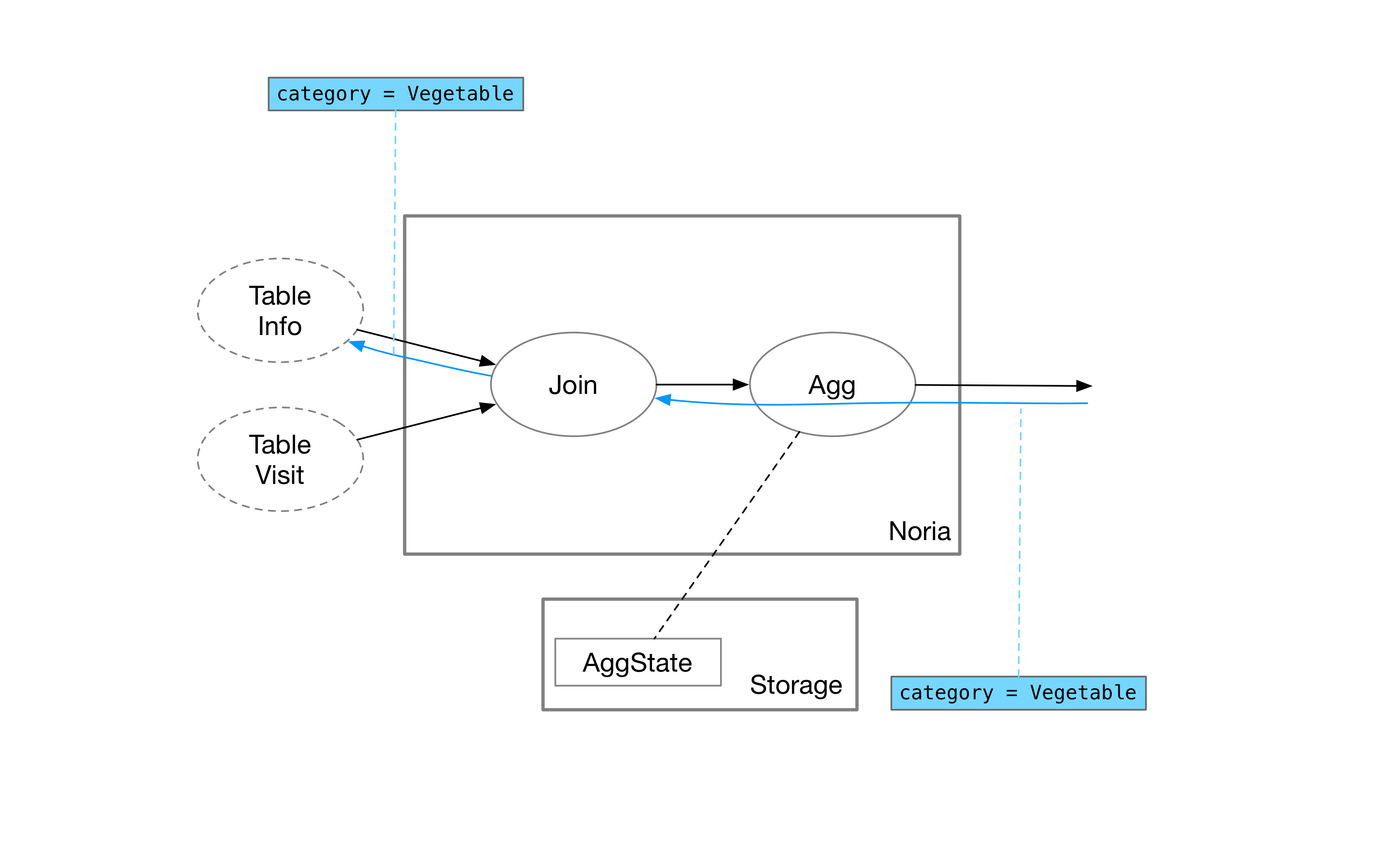
The user queries the maximum value for category = "Vegetable". To compute this result, the aggregation operator needs all records in the vegetable category, so it forwards the upquery to the upstream join operator.
The join operator must obtain all information related to vegetables by querying the two upstream tables separately. Because category belongs to the Info table, the join operator first forwards the upquery there.
Join Operator Implementation
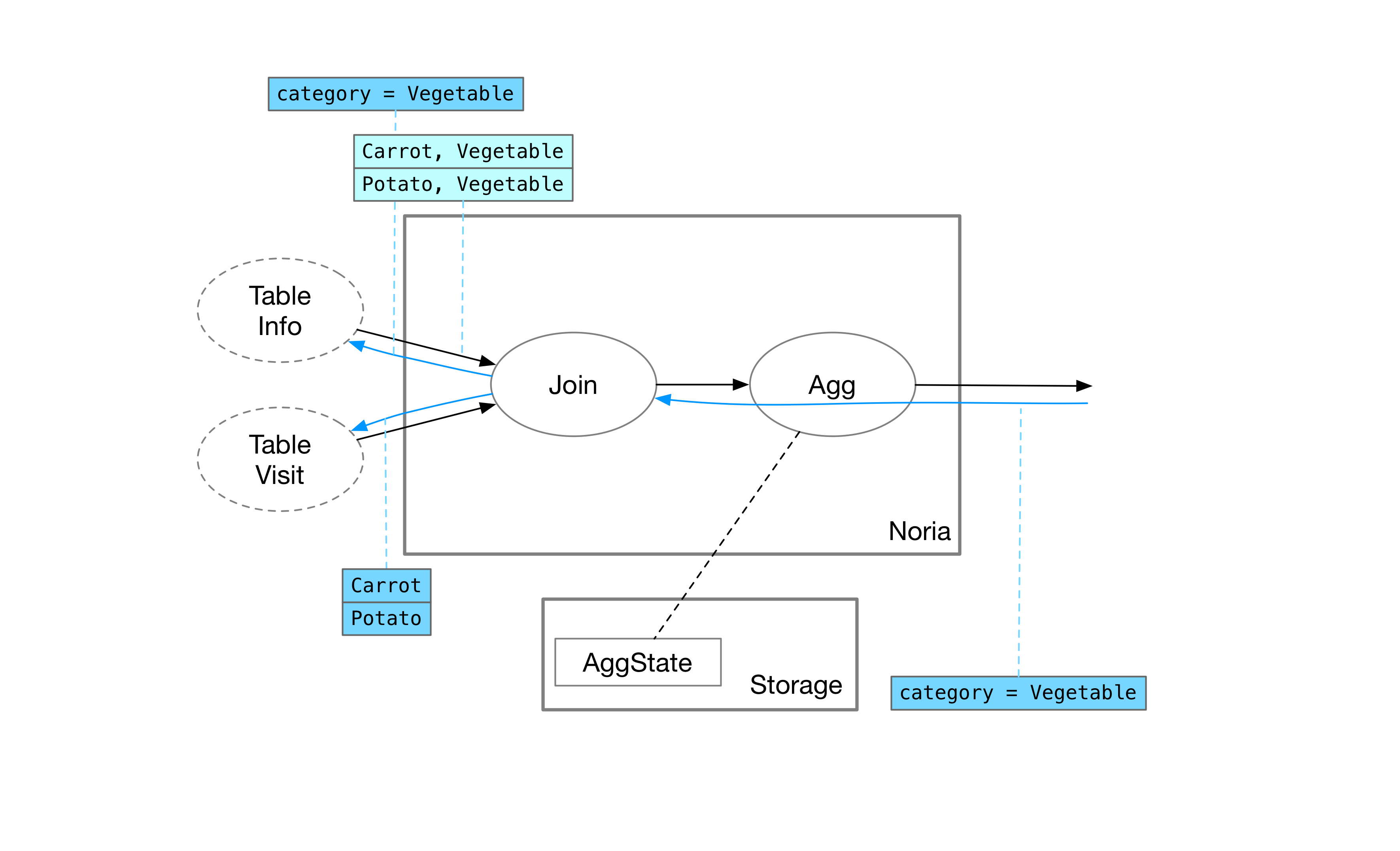
After the Info table returns all products in the vegetable category, the join operator sends an upquery to the other side, the Visit table, for the browsing records associated with carrots and potatoes.
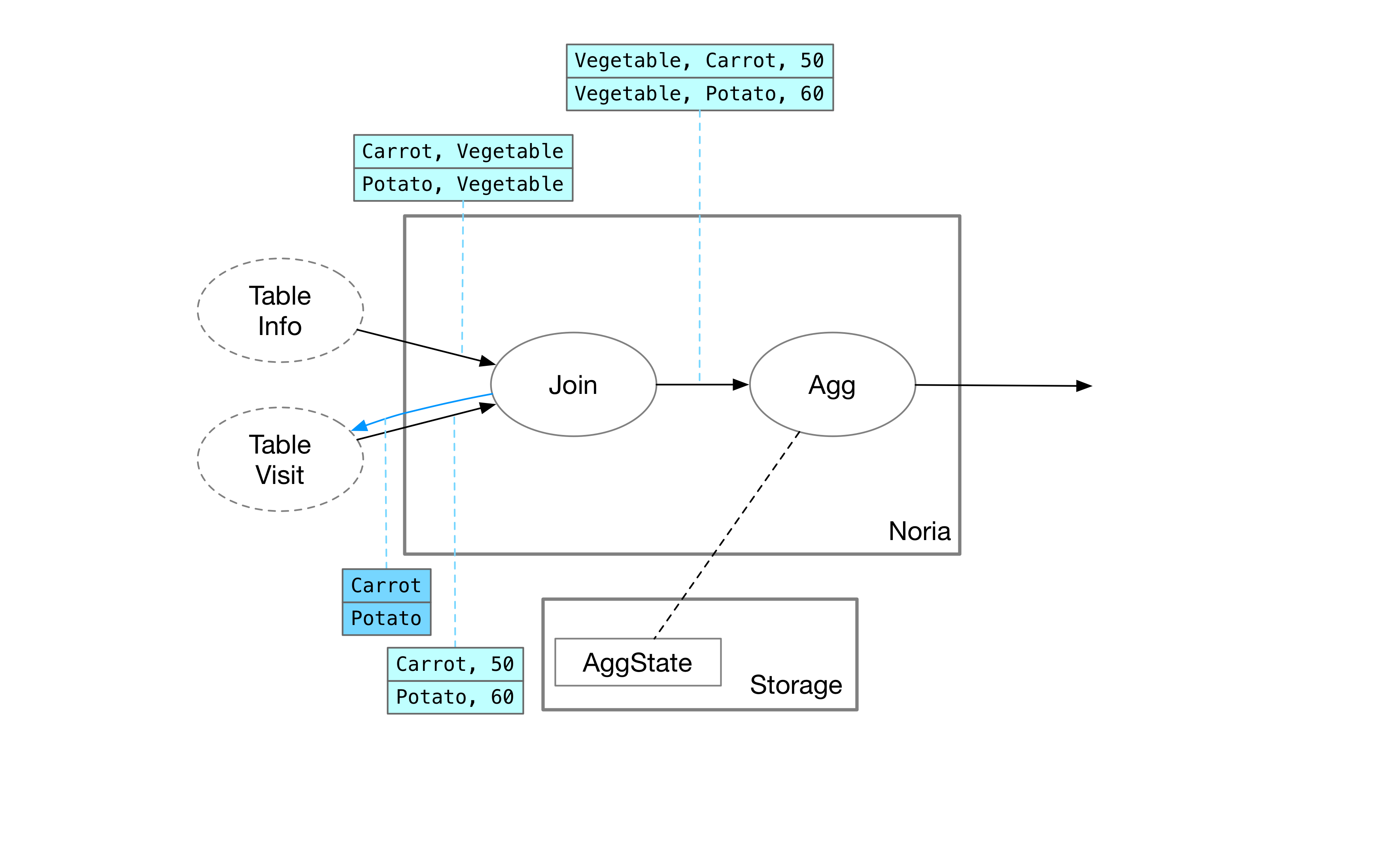
After the Visit table returns the corresponding records, the join operator can compute the join result from the outputs of both upqueries.
In Noria, the join operator does not need to store any data state; it only needs to record the ongoing upquery.
Aggregation Operator Implementation
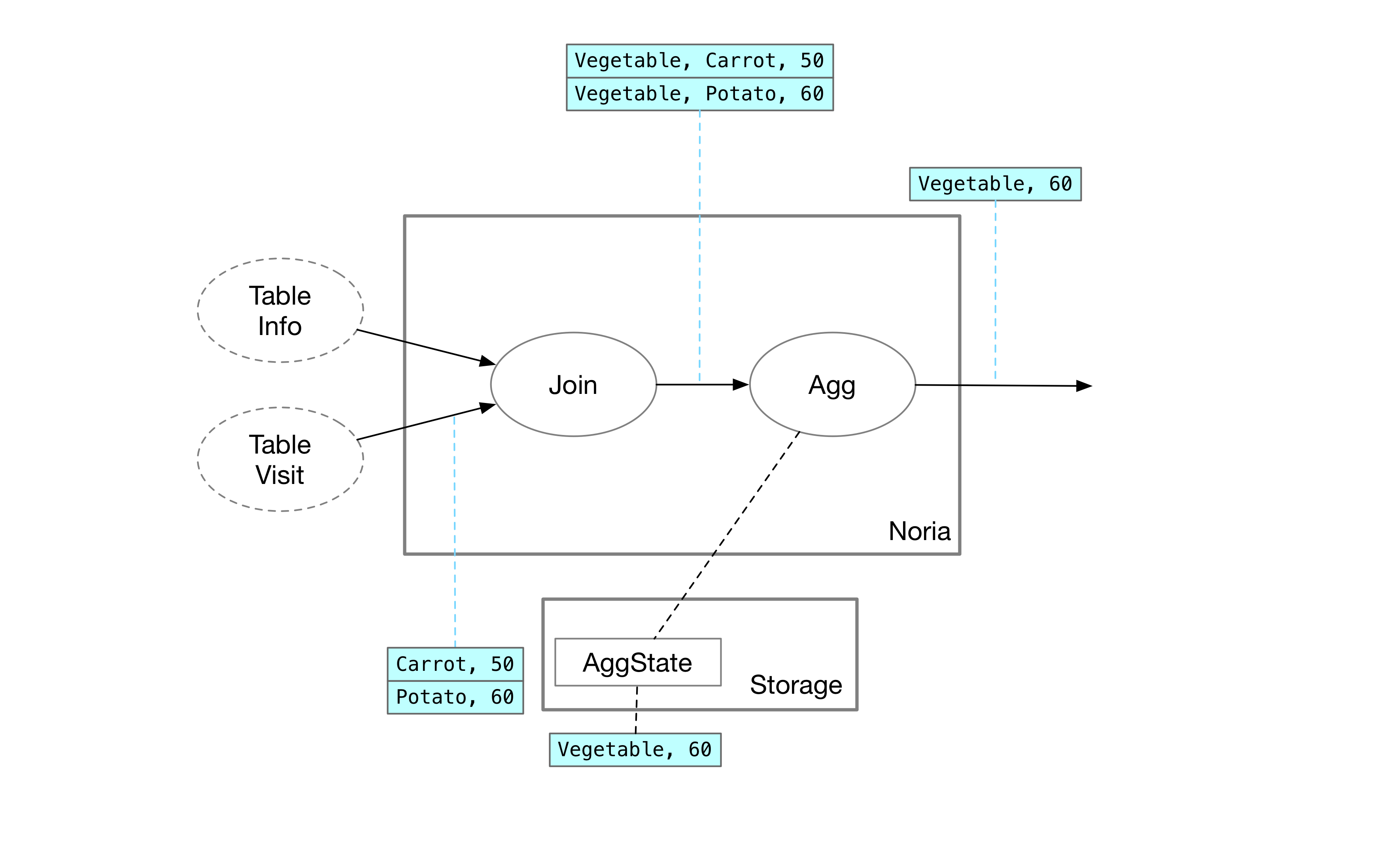
When data arrives at the aggregation operator, Noria calculates the maximum value directly and stores it in the operator’s state. In the systems described earlier, the aggregation operator must store the complete data set (all browsing records for fruits and vegetables). Noria only needs to cache the requested state, so this query records only the rows for vegetables. If a deletion occurs upstream, Noria can delete the corresponding vegetable rows and recalculate the maximum later. Therefore, a partial-state system does not need to record every value so that it can find the second-largest one; clearing the cache is sufficient.
Summary
Stream processing systems that store partial state respond to user queries in real time through upqueries and keep only the minimum state required. They generally have these characteristics:
- Dataflow in the computation graph is bidirectional: data can flow downstream, while upqueries flow upstream.
- Recursive upqueries may introduce slightly higher computation latency than other state-storage methods.
- Data consistency is difficult to achieve. The other storage methods described in this post can achieve eventual consistency more easily. A system that stores partial state must take special care when propagating updates and upquery results simultaneously through the stream, and the correctness of each operator’s implementation must be carefully proven.
- DDL/Recovery is very fast. Because operator state is computed on demand, the system can clear its caches and allocate new nodes after operations such as adding or removing columns from a view or migrating it, without paying the high cost of state recovery.
Finally, let’s compare the characteristics of streaming state stores for different state storage methods:
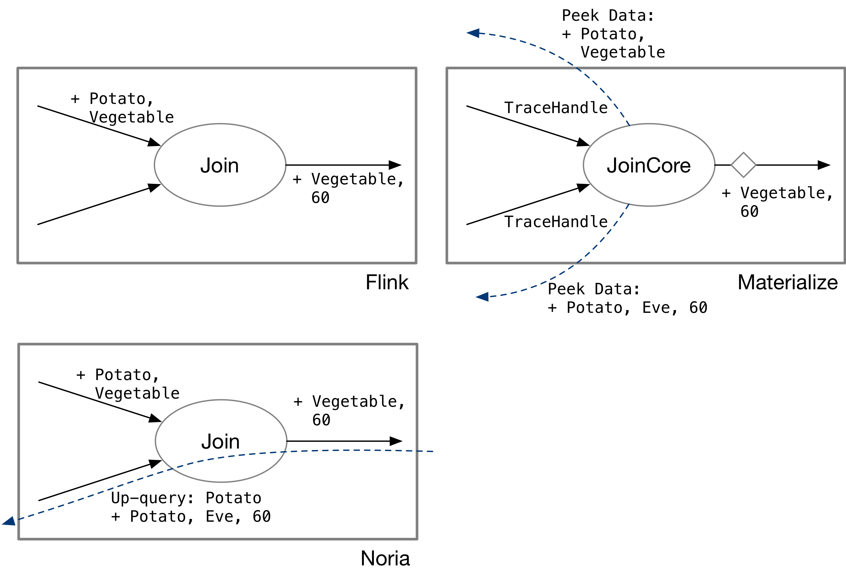
- Full-state storage (e.g., Flink): data flows through the stream.
- Shared-state storage (e.g., Materialize and Differential Dataflow): data and snapshots flow through the stream.
- Partial-state storage (e.g., Noria): data flows downstream, while upquery messages can flow upstream.
References
- Apache Flink
- Flink SQL
- Materialize
- Joins in Materialize
- Maintaining Joins using Few Resources
- differential-dataflow
- Noria
This blog post was translated with ChatGPT from my previous blog post, originally published on January 15, 2022.
Feel free to comment and share your thoughts on the corresponding GitHub Discussion for this blog post.